Physical Address
304 North Cardinal St.
Dorchester Center, MA 02124
Physical Address
304 North Cardinal St.
Dorchester Center, MA 02124

 Introduction
In my last post, I discussed the process of building my Magic Leap One (ML1) view simulator model (hereafter referred to as “model”), and now I would like to show you what the view of the real world will look like through ML1. While I am going to describe and show pictures of the view through the ML1, to fully appreciate the visual intrusion, you will simply have to try it for yourself. To this end, the 3-D printable files (in STL format) of the model are included in Appendix A.
Understand that this model has none of the diffraction waveguide optics (what Magic Leap has hyped as “photonic chips”) that will further distort and diminish the view. This “view model” is simply the best case view of the real world through the ML1. Any optics in the way will only worsen this view.
I have modeled the ML1 as closely as possible with respect to the view through it based on the available evidence. I’m providing the model I used so others can verify or challenge my results and cut through the debates about whether it will look different based on how the human visual system works, which is, of course, different than a camera.
Almost everything in this article is hiding in plain sight. One look at the headset and any expert should know that the view of the real world through the ML1 is going to be poor. It’s unbelievable to me that nobody, at least that I have seen, has written about the real-world view is through the ML1. I just went to the trouble to prove it in some detail.
I discovered a key piece of information about interpupillary distance (IPD) in the recent Magic Leap application US 2018/0052277 (‘277) that serves to better scale the 3-D model of the ML1 (see Appendix B: How the Sized of the Magic Leap One Model Was Scaled below). The result was that I found I should reduce the model linearly by about 10%.
It turned out that the IPD given in the patent application was very close to my own IPD and was the value I used for centering the camera used to create the images. Other users might not be so lucky.
The picture below gives a good idea of how the real world looks through the ML1. The resultant image is a composite I made to model the view with both eyes open. For reference, I have included the unobstructed view along with views through the left and right light tunnels in the thumbnails below the simulation.
The lens and camera combination has a field of view (FOV) of 96° horizontal, 73° vertical, and 106° diagonally. The picture’s FOV is close to that of the Oculus and HTC Vive. The source pictures were shot at f3.5 to simulate the focus blur seen by the eye. I have also indicated in the display image the rough size and location of the display image’s exit pupil expander (EPE) and thus the maximum displayed image size. As stated previously, this simulated view does not show the further image quality issues caused by the waveguide’s glass and six layers of diffraction gratings on the real-world.
Perhaps the biggest distractions are the tunnel ring ghost images and something I consider a major design flaw with the ML1. The rings are caused by light tunnels blocking the view on the nose side by each eye (more on this issue in a moment).
Eyeglass lenses are typically about 13mm from a person’s eyes plus or minus 2 mm, and the only 3mm to 5mm thick. But the ML1 light tunnels are about 15mm from the eye, more importantly, extend to about 44mm on the top and 37mm on the bottom of the eye. The eye’s FOV is wider than the tunnels, and thus each eye sees the sides of the tunnel all the way to its end, and the view is blocked.
The image below left shows some key (corrected) measurements from a scaled drawing taken from an earlier Magic Leap design patent. Below center is from Figure 113B of the Magic Leap patent application 2018/0052277 that shows a heat signature from a straight-on view of an actual (but maybe not final) device that nicely outlines the waveguide. Below right is a series of pictures showing an outside-in and inside-out view of a light tunnel.

Both from the “fit” of the head shown above left and from my personal wearing of the model, I have estimated that the eye is about 15mm from the start of the lens tunnel. The size of the entrance to the light tunnel is ~36mm, and the exit is ~43mm (see the left diagram above and Appendix B).
I added the calculated size of the exit pupil expander (EPE) of the waveguide in the location where it appears to be, based on the available evidence in Fig. 113B. The EPE limits the maximum size of the image (the image has to be smaller than the EPE), and the angle from the eye to the image from the EPE reveals the FOV of the display. Some rough calculations put the maximum possible FOV of 46.1° horizontally, 27.9° vertically, and 54° diagonally.
There is a “light block” I have shown in Fig.113B at the bottom of the lens tunnel that I have observed in both pictures and videos of the ML1. I don’t have conclusive evidence as to what the ML1 does with sides #2 and #3 of the waveguide marked on Fig. 113B. There, either the light is completely blocked, or there will be an out of focus effect due to the edge of the waveguide refractive mismatch, but this has not been modeled or simulated in the images.
Usually, binocular disparity (difference in view between each eye) is used by the human visual system to determine the apparent difference The eyes “verge” (turn) to make the two views line up, and this is interpreted as depth (how 3-D stereo images work). But since the left and right eye have different parts of the ML1 in front them, the human visual system overlays them as semi-transparent (ghost) images.
 The chart on the left shows the angular FOV of a single eye with the eye not moving in white on black. Overlaid in purple is the view of eye movement. In red I have indicated the FOV through a single light tunnel with the area blocked by the ML1’s body and temples pattern filled. The rough size of the displayed image is in the cyan rectangle.
As readers of this blog may know, the human eye’s resolution falls off dramatically from the center of vision to the outsides, and the human optical system will adapt and emphasize the image in the center, so-called, “tunnel vision.” At the same time, the eyes are constantly moving and building up a higher resolution and wider view than they can see in a single instant, but the tunnel effect of the ML1 cuts this off.
At the simplest level, the ML1 cuts off most of a person’s peripheral vision and with it a sense of immersion including visual cues, thus necessitating movement of their eyes and head.
 As I have previously written, the various pictures and videos of the ML1 show a significant darkening of the real world by the glasses. My original estimate was that the ML1 blocks about 85% of the light, but when I redid the estimate, I came up with about 80%. For the model, I found some sunglass lenses (at a local dollar-type store) that block (as measured by a light meter) 80% of the light.
The human eye will adapt by opening the iris to let in more light, but that will reduce the person’s visual acuity (and thus why there is brighter “task lighting”). The human visual system will adapt, but it still causes a significant dulling of the real world. The opening of the human iris will also reduce the eye’s ability to focus (which is why “task lighting” is brighter).
If you light a room appropriately, it becomes about five times darker than it should be when you look through the ML1. Put on the ML1, and everything is now too dark, and this is before you include the issues with looking through the waveguide diffraction grating.
The ML1 model I made happens to be almost an exact match for my IPD and that of my camera location. It’s not clear what Magic Leap will do with the wide variety of head sizes and IPDs.There is not a one-for-one correlation between head size and IPD. I guess it is just tough luck if you have a large head and narrow set eyes.
Magic Leap has said they are going to have different sizes for different sized heads, but they have said nothing about what they are going to do about the wide variance in the interpupillary distance (IPD). There is no IPD adjustment for the view through the headset to the real world as it is non-adjustable and molded into the case.
I would assume the ML1 at best has “electronic IPD adjustment” for the display; a way of saying that they crop/reduce the display image size, so they can move it left and right. But there is nothing they can do for the IPD mismatch with the real world.
According to various studies and quoting a Cambridge University Paper:
“The key results are that mean adult IPD is around 63 mm, the vast majority of adults have IPDs in the range 50-75 mm, the wider range of 45-80 mm is likely to include (almost) all adults, and the minimum IPD for children (down to five years old) is around 40 mm.”
Not only will headset sharing impractical, but it is hard to imagine them having enough variations to serve most people. Even with the IPD of the view tunnels being nearly ideal for me, the view out is lousy; it only gets worse from for those that are mismatched.
Based on the ML1 design (see Fig. 110E below), it looks like they will need different waveguides and significantly different headsets to support even a modest range of IPDs and head sizes.
 When smart people do something this bad, the answer is almost always some combination of, “the alternatives at the time seemed worse,” “the person at the top decided,” and “we just had to get something out.” The hope inside the company becomes, “maybe people won’t notice.”
Patent application US20180052277, Fig. 110E gives some clues as to how they ended up with a non-adjustable design that blocks so much of the real-world. It comes down to working back from the diffractive waveguides. Projectors 11010 in Fig. 110E are in the temples of the ML1 and connect to waveguides 11001. To make them adjustable, the whole projector and waveguide assembly would have to move.
But the projectors can’t move toward the center as they would run into the person’s head.
You might think to look at Figure 110E, the tunnels look shorter than the ones in the ML1 model, but that is because you only see about half the tunnel. The other half of the tunnel continues into surface 11008 as seen in figures 111C and 111D below (see a red line connecting 111C and 111D).

They could have made the waveguides wider or added other optics, but this would make the optics more expensive and hurt the display image quality. Additionally, the temples of the ML1 would have to be much wider to accommodate the movement of the projectors resulting in a bulkier, heavier, and more expensive design. Rather than solve the problem, Magic Leap has chosen to ignore it.
I have low expectations for the display’s image quality based on the available technical information. They are doing a bunch of things with known problems. Its also appears from the design that they kept making tradeoffs in favor of size over image quality.
As I have been writing about Magic Leap for over a year and as verified in the 2018/0052277 patent application is doing exactly what I was expecting. Magic Leap is not doing anything that different from Microsoft’s Hololens, Vuzix, Digilens, and Waveoptics among others. They are going have all the problems associated with diffraction waveguides, only worse, as they have twice the number of layers due to the two planes.
They are using field sequential color LCOS microdisplay like Hololens, Google Glass, and most other AR headsets. This means they will have field sequential color breakup and limited contrast. Only the ML1’s optical path is more torturous which means the image quality should be further degraded.
Rony Abovitz, the CEO of Magic Leap hyped in the December Rolling Stone Article:
“The world you perceive is actually built in your visual cortex,” he [Abovitz] says. “The idea is that your visual cortex and a good part of the brain is like a rendering engine and that the world you see outside is being rendered by roughly a 100 trillion neural-connections.” “You’re basically creating the visual world,” he says. “You’re really co-creating it with this massive visual signal which we call the dynamic analog light field signal. That is sort of our term for the totality of the photon wavefront and particle light field everywhere in the universe. It’s like this gigantic ocean; it’s everywhere. It’s an infinite signal, and it contains a massive amount of information.”
The very few, very short, videos released by Magic Leap so far, plus the reports by the author of the Rolling Stone article is that the demos are all in dark rooms with very limited and controlled lighting. Magic Leap’s “solution” to the visual garbage they present to the eye is to darken the real world so much that it does not bother you so much.
The visual intrusion of these headsets on the user’s view of the real world is simply terrible. Even if Rony Abovitz’s snake oil pitch above were true, what difference does it make if they are presenting to your “visual cortex” the visual garbage of the headset located between you and the real-world image? What Magic Leap proves with the view of the real world, they don’t give a twit about your visual cortex; it is all just marketing hype.
 To fully appreciate the ML1 view issues, you must see it with your own eyes. To that end, I decided to provide the 3-D printer files of the model and the various other structures I’ve built. I’m far from an expert in 3-D CAD, so these models are very simple. I primarily focused on getting the size, shape, and positioning of the light tunnels and overall shape as close as possible based on the available evidence.
I developed these models myself, and I am granting a free license for public and private use. The only restriction is that you give credit to KGOnTech if you use them publicly and that you don’t make a profit from them.
I put all the models in a compressed ZIP directory located HERE (about 8 megabytes). The files are listed below.
If you want the full experience, you will need to get some large sunglass lenses. I found some at a local “dollar-type” store. I simply popped them out of the cheap sunglasses and cut them down with some heavy-duty scissors and taped them to the front of the light tunnels (I used some double-sided mounting tape).

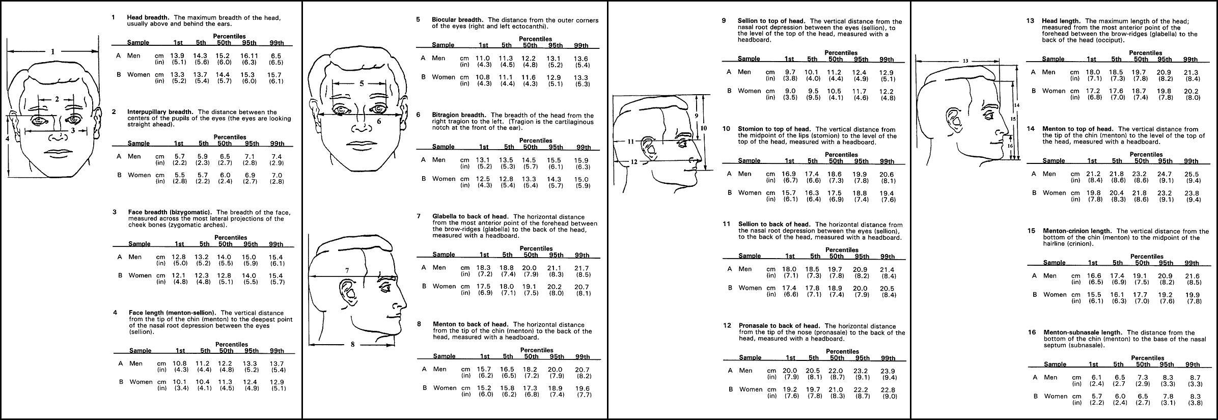
I started considering what the view of the real world through the Magic Leap goggles looks like by using estimates made by Sarah Kimberly Eusche’s analysis on her blog SAKIE using Patent D797,735 (‘735) and a table of the range of feature of the human head to help add dimension to the dimensionless patent figure.
Magic Leap patent application US 2018/0052277 (‘277) was published after Sarah’s work and included some detailed figures including Figure 35A (top left) which show and IPD of 60mm. While the IPD is not discussed in the Patent, it is shown in Figures 35 A to H. The heat signature images of the internals of the Magic Leap headset given in Figure 113B of the ‘277 which shows the outline of the waveguides. Overlaying figure 113B with figures from ‘735 in the middle two figures at left and using the IPD of 60mm is then used to scale the image. Based on this new information, it turns out that Sarah’s estimates were about 10% linearly too large. Based on this analysis, I rescaled my 3-D model of the headset.
Fortuitously, an IPD of 60 degrees is very close to my own IPD and was what I was using for my camera rigs. To give you an idea of scale and how the ML1 cuts into the FOV relative to glasses, I took a picture with my glasses held in the model as I would wear both of them.
 While last time I showed a rig I used, at first I had a lot of trouble with consistently positioning the ML1 model. I developed a “dual lens cap holder” that would allow me to mount the view model onto the lens in place of the temples. This rig had built into it just the part of the temples that the camera would see to create the light blocking of the temples in the image. It positions the front center of the lens at the calculated location of a person’s eye. This location is approximate as the lens on a camera is not identical to the eye.
I mounted the camera on a tripod and took pictures of the room with the “cap” off and lined it up with the left and right eye tunnel. I took pictures from where each eye would be located with a wide-angle lens (Canon EF-S 10-22mm lens with a 10mm f/l at f3.5 in manual focus with the focus near infinity on Canon 70D). The combination of lens and camera provides an angular FOV of 96° horizontal, 73° vertical, and 106° diagonal.
To generate the mask, I shot images for the left and right eye inside a photo tent to get a white background. The left and right mask images were aligned based on how the images aligned in the room pictures. The mask was generated by taking 50 percent of the left and right image followed by doing an unsharp mask operation to enhance edges similar to the way the human eye perceives edges (I adjusted the radius and amount of unsharp-mask to match what I saw roughly). This mask was then used with the unobstructed view (from one eye) to create the final image which gives a reasonably good representation of the image as seen with both eyes.
In addition to the Canon 70D with a rectilinear (normal) lens, I tried an Olympus FourThirds camera with a 7.5mm fisheye lens with its lens-cap-rig to position the front of the lens about 15mm from the M1 model. The fisheye gives a wider FOV (180 degrees diagonally) but much more distorted. The fisheye is a bit closer to the FOV of the human eye. I have included the comparison to the Canon APS-C with a 10mm focal length linear lens to the Olympus FourThirds with the 7.5mm fisheye, both at f-number 3.5. Below the comparison is a simulation with a mask I generated with a similar procedure as I used for the Canon 10mm rectilinear lens. For these pictures, I removed the sunglasses’ darkening lens.


I would like to thank Ron Padzensky for reviewing and making corrections to this article.

Wait. Are you saying that the people that bet $2B of OPM didn’t really know what they were getting into? Or that the HoloLens/2015 pretty much does everything better than ML1/2018 ? Rony seemed like such a visionary…
Why would Google bet so much on something that SBG Labs (now you guys know of them as Digilens)+Rockwell Collins productized in 2009? Where is the moonshot high concept product that they claimed to be after or GV claims to invest in? LCoS+DHOE is so banal that they are covered in microdisplay textbooks from mid-2000s. I believe a case could be made for misrepresentation if ML product doesn’t quite meet expectations.
Another point – The HoloLens went to town with the most obvious system design that could be conceived over a group ‘brainstorm’ meeting (apparently). They picked the lowest hanging fruits. So ML’s design choices seems to be driven by the need to look aesthetically different without being substantially different.
“Wait. Are you saying that the people that bet $2B of OPM didn’t really know what they were getting into? ”
In short, yes.
Rony spouts mostly gibberish.
Look at the patents I have cited.
ML made a different set of terrible choices, many of which are worse than Hololens.
You have to be careful with one assessment, the 2bio was not a single source capitalization, Google has put around $542 million into ML, a lot of money per se, but not so much for a behemoth like G. Look at the price tag of Occulus when FB acquired them in comparison.
A lot has little to do with product interest, but rather with having a foot into possible viable IP downstream, specially when you look at the competition angle between companies such as Microsoft, Google, FaceBook.
[…] “The Magic Leap One Experience” (ML1’s Terrible View of the Real World) 2 by GW150914 | 0 comments on Hacker News. […]
[…] Modeling the Magic Leap One Experience 100 by GW150914 | 44 comments on Hacker News. […]
[…] last blog article on the Terrible View of the Real World through the Magic Leap One made the Top Story on Hacker News. That good news set off a series of events that took the site […]
[…] zu überführen: Basierend auf Patentskizzen und den ersten Fotos der Magic-Leap-Brille baute er einen Prototyp des Brillengestells für den […]
[…] über “The Magic Leap One Experience” (Part 2, ML1’s Terrible View of the Real World) — Karl Gutta… […]
Amazing Analysis, as always. I tried in the past to infer something about the FOV from the emulator and there the (horizontal) FOV seems around 60° or 45°, depending on which part of the emulator you look at. (https://skarredghost.com/2018/03/23/magic-leap-ones-field-of-view-making-assumptions-from-the-emulator/ for who is curious). Considering also O. Kreylos evaluations, I guess that in the end we’ll actually get something around 40°-45°, that doesn’t seem enough for me to be a true competition of Hololens. HL3 should come out with something around 70° according to a patent and would destroy completely Magic Leap.
I met engineers not working for ML who have tried it and were very impressed by the realism and rendering as well as other features which do not exist on the other MR headsets today. FOV was always a challenge; and, for example, we can see the impractical form factor you would need for improved FOV from LM’s North Star recent design.
I wrote about what I call the “Pixel Gap” a while ago (https://www.kguttag.com/2017/06/07/gaps-in-pixel-sizes/) and how this fundamentally drives everyone. If you work from a directly viewable display (as in cell phone size) then you get a wide FOV and large chunky pixels with low detail and can only display simple text. If you start with microdisplays, then you get very small pixels and get fine detail but a small FOV. If you have a big display, you need very big optics and you can really only afford in terms of cost and weight a simple combiner (Leap Motion’s Northstar, Meta 2, Mira, etc.). Or you go the microdisplay route and it is hard to get much more than 50 degrees.
ML1 appears to be essentially a VR headset that lets you see a little bit of a dim/darken real-world. It is going to have much finer resolution (by about 4x linearly or 16x in area) of a typical VR headset. But it is going to also have a much smaller FOV, lower contrast, poor color uniformity across the field, more reflections/ghost artifacts, and many other problems. As a walk around AR headset ML1 is going to be worthless/dangerous. Sometimes engineers get focused on the one advantage and ignore the whole picture (figuratively and literally).
To have a viable product, you have to build something that you can make for a price at which people can afford and see the value at the price (very basic).
[…] by /u/SkarredGhost [link] […]
This is like commenting in 2007 how bad is the iPhone 2G because the screen could be 3 times bigger and the bright is not good enough…
Technology needs small steps to move forward, even when having the hugest budget on Earth.
[…] 3-D prototype to explore the view through the Magic Leap One and some of the ergonomics. I wrote a series of articles on my conclusions. BTW, the 3-D printed model turned out to match the view through the actual device quite […]